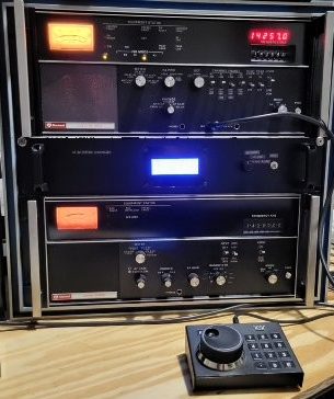
Collins HF-8014A Exciter HF-8050A Receiver Frequency Synchronization
The HF-80 system was a major military/government communications platform, but its adaptability Ham radio can be an issue. This page will look at how to get the receiver and exciter on the same exact frequency and phase locked using one oven frequency standard (TCXO).
Detailed Discussion
There is no way to get around the complexity of the HF-80 system and the extensive document manuals illustrate this point. This page and others are an attempt to reduce the complexity to a practical level. There are three ways to use one TCXO to feed the receiver and exciter with one frequency reference: 1) Use an external frequency standard of 1mhz, 5mhz or 100khz. 2) Use the TCXO in the HF-8050A if present, 3) Use the TCXO in the HF-8014A if present. This area of the HF-80 system is optional. The base no option setup is no oven frequency standard in either receiver or exciter. My HF-8050A came with only the base non-temperature compensated crystal oscillator. However, my HF-8014A came with a 1mhz frequency standard. Therefore, I would use that standard to be the HF-8050A’s frequency standard as well.
I encountered two problems: 1) The HF-8014A did not have the Frequency Standard Switch option (646-6558-001) that allows the internal frequency standard to be sent out externally. 2) The receiver did not have the AC-8013 External Standard Kit (622-3461-001) option that allows an external frequency standard to be used. These options are not available from any of my known sources. However, I did have the manuals for both these options which included a schematic and BOM, and I was able to fabricate a functional but not exact replacement.
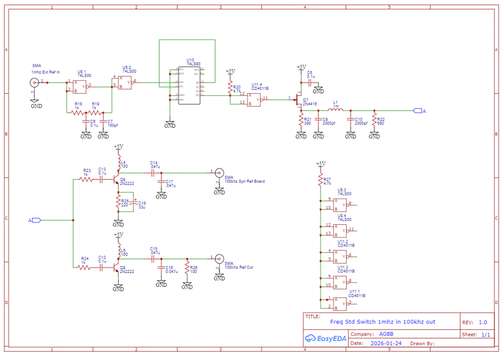
A Functional Frequency Standard Switch Replacement
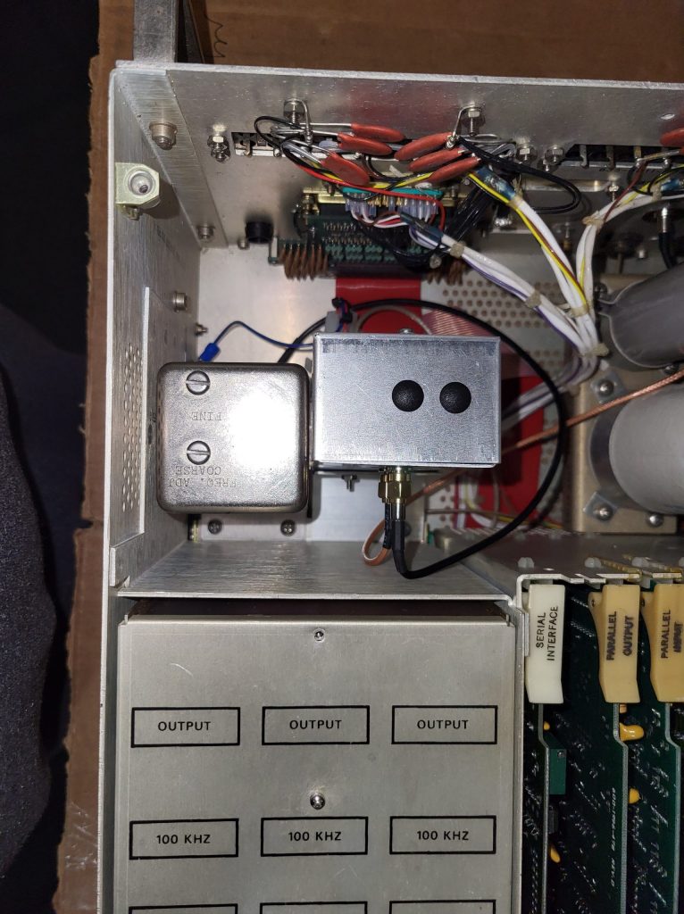
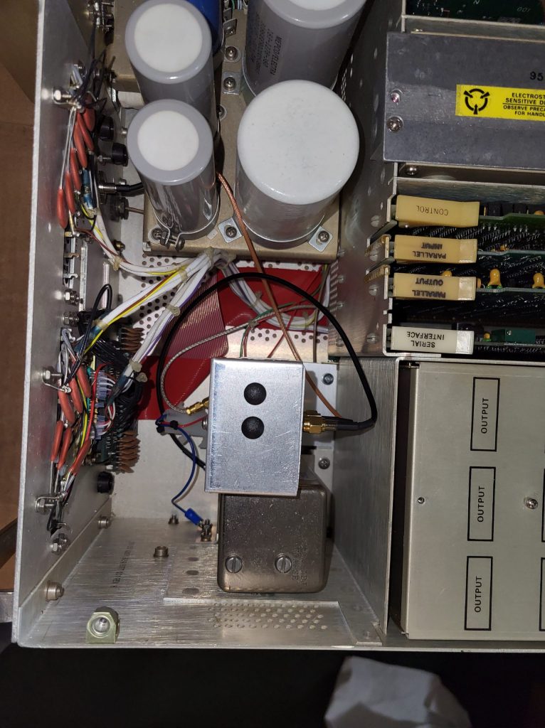
Below is the schematic for the replacement Frequency Standard Switch. I did not design a pc-board (pcb), but instead, built it on a piece of perf board that has a ground bus and tinned solder pads. I encourage anyone to design a pcb and I will add the pcb file to the page download. The pcb was mounted in a 2×5 Bud aluminum box that used SMA bulkhead connectors. The connector on the Frequency Standard is an SMC type, so an SMC male to SMA male adapter cable is needed. These adapter cables are available on Ebay. +5V must be brought in from the HF-8014A power strip. There are two 100khz outputs: 1) the external 100khz that has an SMA bulkhead mount connector. A 1 ft SMA male to female BNC bulkhead adapter cable is used to output the signal to the HF-8014A’s rear panel Ext Freq Std hole. Again, some specialty cable vendor will have these on Ebay. Note that these BNC bulkhead connectors have a larger footprint than the standard BNC bulkhead connectors. The cable has to be fed through the rear panel from the outside not the inside. Below are a series of pictures that show how the Bud box is mounted and the cable routed. The two 100khz output SMA bulkhead connectors were initially located on the top end of the Bud box; but had to be relocated to the side of the box due to interference with the top chassis cover.
A Functional External Std Kit
This kit consists of two things: 1) An External Phase Lock board that mounts on the A16 Synthesizer Reference card. 2) A 2 ft female BNC bulkhead connector with flying leads is mounted to the HF-8050A rear panel in the hole J23, labeled Ext Freq Std. Remove the bottom cover of the synthesizer assembly and install cable W1 to the synthesizer sideboard as follows: 1) thread cable W1 through rubber grommet. 2) Solder center connector of W1 to J2-A post or pad of synthesizer sideboard. 3) Reinstall synthesizer assembly bottom cover. The AC-8013 External Standard kit (622-3461-001) manual will provide more details.
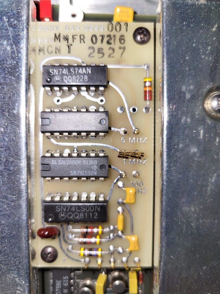
The External Phase Lock board (635-0655-001) is an optional printed circuit board that mounts to the synthesizer reference and allows an external frequency standard to be used. This card uses a 5-pin connector to mate with the synthesizer reference. A schematic of this board and a picture of it mounted to the synthesizer reference is shown below. Again, this board is an option that is no longer available. As shown in the schematic, the board is fairly simple and straight forward to build on .1″ perf board. Using five standard .1″ pins that were mounted on the perf board made a functional 5 pin male connector that plugged into the synthesizer reference. The below picture shows a picture of an actual Collins External Phase Lock board, not the one that I created with perf board. I failed to get a picture before installation.