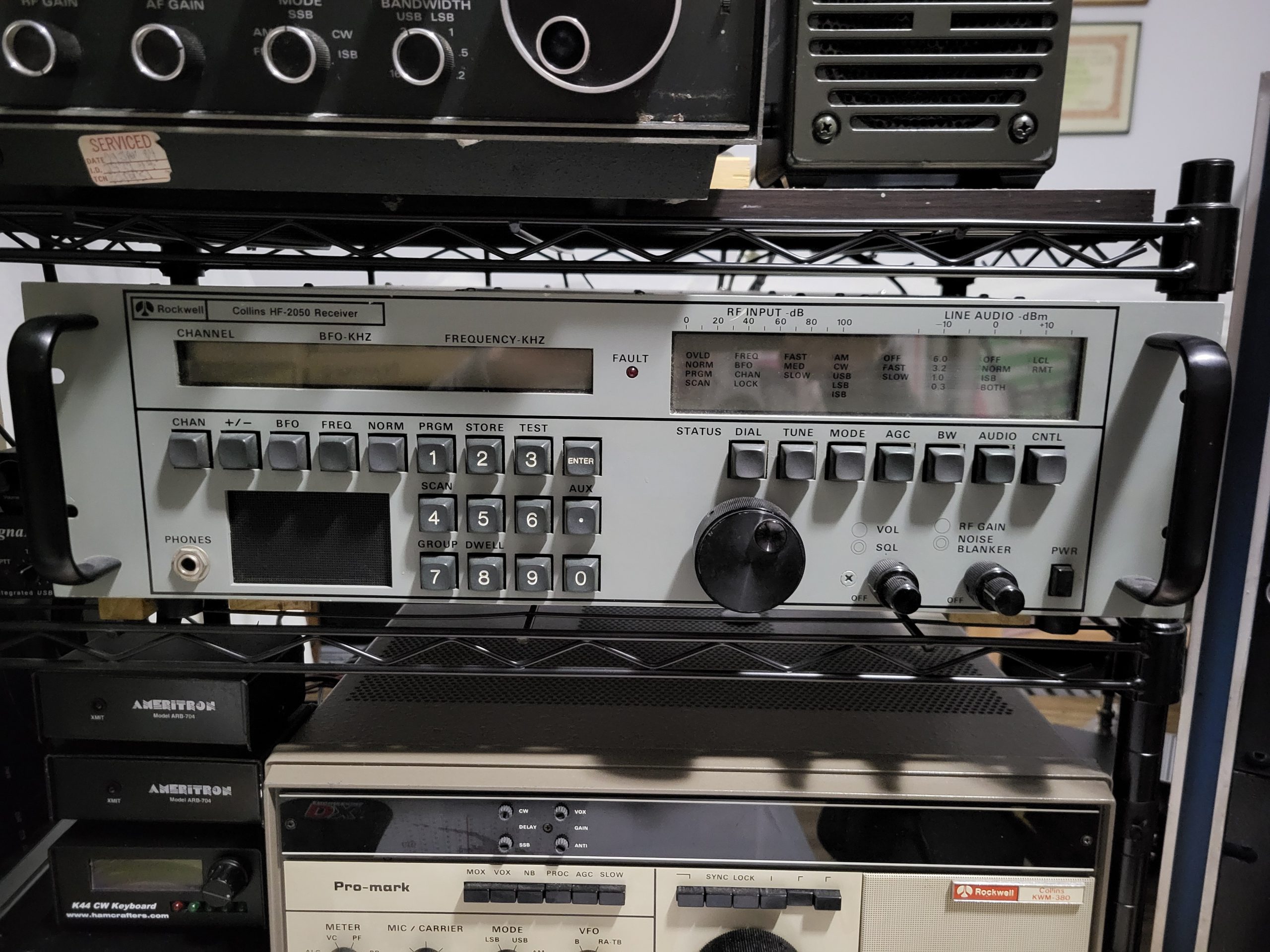
Collins HF-2050 Receiver Integration with the HF-8014A exciter
The HF-80 system was a major military/government communications platform, but its adaptability Ham radio can be an issue. The 851S-1 is not the only receiver that can be used with the HF-8014A. This page will discuss using the Remote Control port of the HF-2050 to extract frequency information using Monitor Status commands to set the HF-8014A exciter frequency to the HF-2050 frequency with a touch of a button. If the HF-8014A frequency standard is set to output 100khz and cabled to the HF-2050 100khz Ext Ref Input, the two systems will be exactly on frequency.
Detailed Discussion
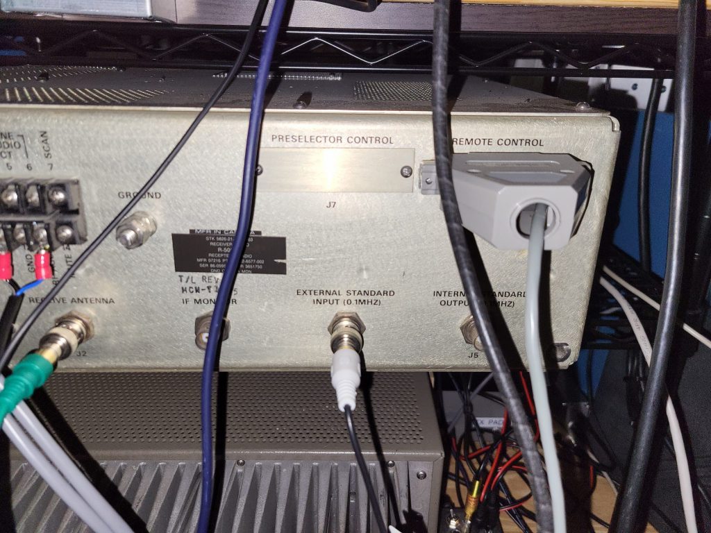
The HF-2050’s Remote Control port, J6, is an RS-422 port that can be used to get Monitor Status information from the receiver even when it is not in Remote Control Mode. If the receiver’s Remote Control port is polled on a timed basis, the HF-80 System Control will always have the frequency displayed on the HF-2050 front panel. There will be a slight delay as the frequency tune knob is turned. The HF-8014A frequency will be updated when the appropriate function key is pressed and a Tune cycle will be initiated.
Requirements
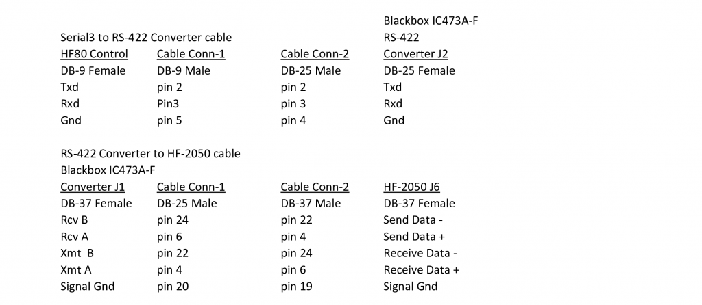
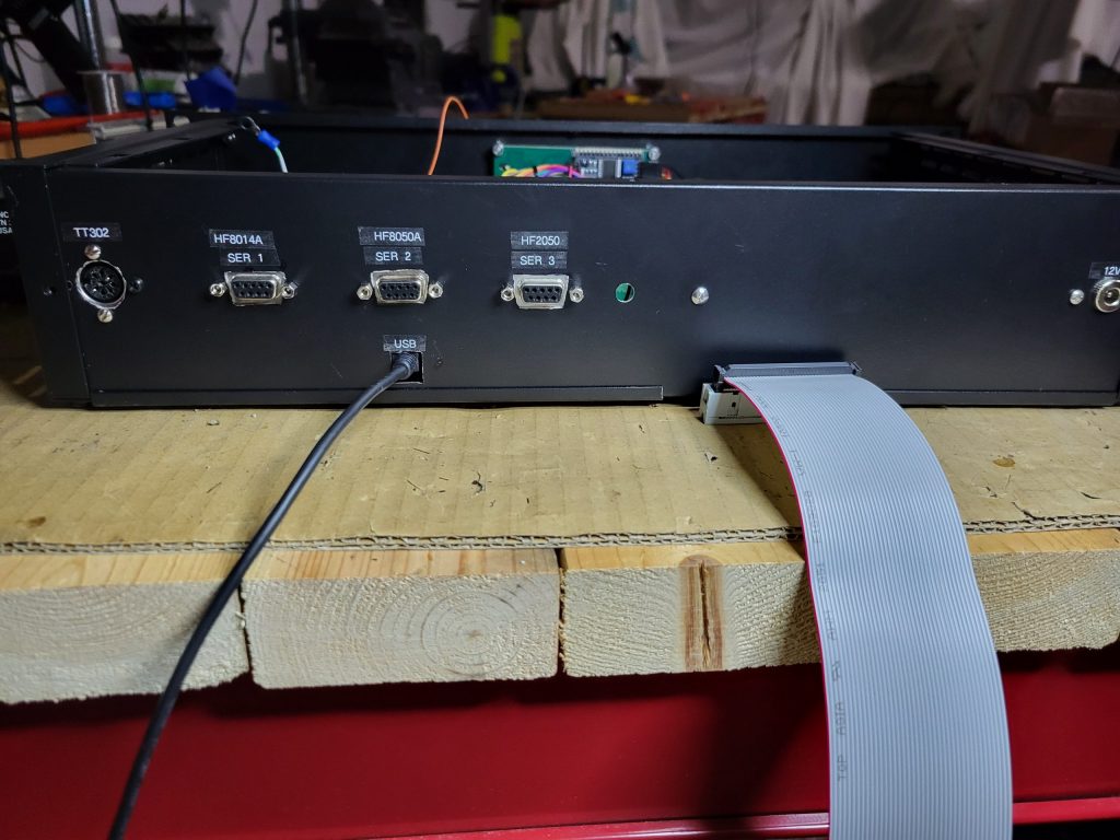
The following are required: 1) An RS-232 to RS-422 converter. 2) A DB-9 male to DB-25 male cable whose construction is described in the Serial Port cable document. 3) A DB-37 male to DB-37 male cable whose construction is described in the Serial Port cable document. The RS-232/RS-422 converter that I use is an old Black Box model IC456A-R3. If you use a different RS232/RS422 converter, then the cabling will probably be different. The DB-9 male connector plugs into the far-right DB-9 socket on the System Controller’s rear panel. 4) Setting the HF-2050 Remote Control port to the following settings: 9600 baud, odd parity, and 1 stop bit.
Operation
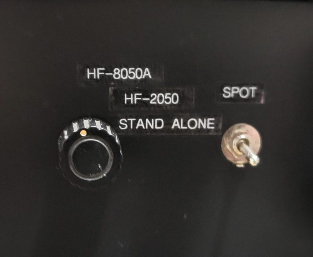
Before powering up the System Controller, setup the Rx Selector switch to HF-2050. Under this selection, the System Controller will get its power from an external 12v power source. Turn the HF-2050 on first and then the System Controllers +12v. The System Controller should indicate HF2050 on the second line on the right side of the LCD display. The HF-2050’s currently displayed frequency should also be displayed on the top line of the LCD display. When you find a frequency that you would like to have a QSO on, push the F1 function key on the TT-302R keypad. The HF-2050 frequency should be immediately sent to the HF-8014A exciter. If you’re using the HF-802x PA, a Tune Cycle will be initiated. If you are operating split frequency, the System Controller has the ability to quickly swap the transmit frequency with the receive frequency so that you can find the frequency of the station that a DXpedition is currently working. Likewise, you can quickly swap the frequencies back. This could be a problem for the HF-8021 PA because it could initiate a Tune Cycle every time this action occurs. With my PA setup, this is not a problem.
Serial Communication to the System Controller
The System Controller uses serial communication with the HF-2050 to get Monitor Status information, specifically the current Frequency and Mode. The serial protocol used is the 7-bit ASCII protocol. The serial port configuration is 9600 baud, 7 data bits, odd parity and 1 stop bit. The HF-2050 serial port configuration switches must be set as follows: Set the HF-2050 A2U39 switch settings for 9600 baud: S1=off, S2=on, S3=off, and S4=off. The address is set to 15, or ox0F hex, which would require all of the address straps to be open. This Monitor status information is used for frequency control of the HF-8014A.
Shown below is the table for the serial cable construction.