Mackay 3010C
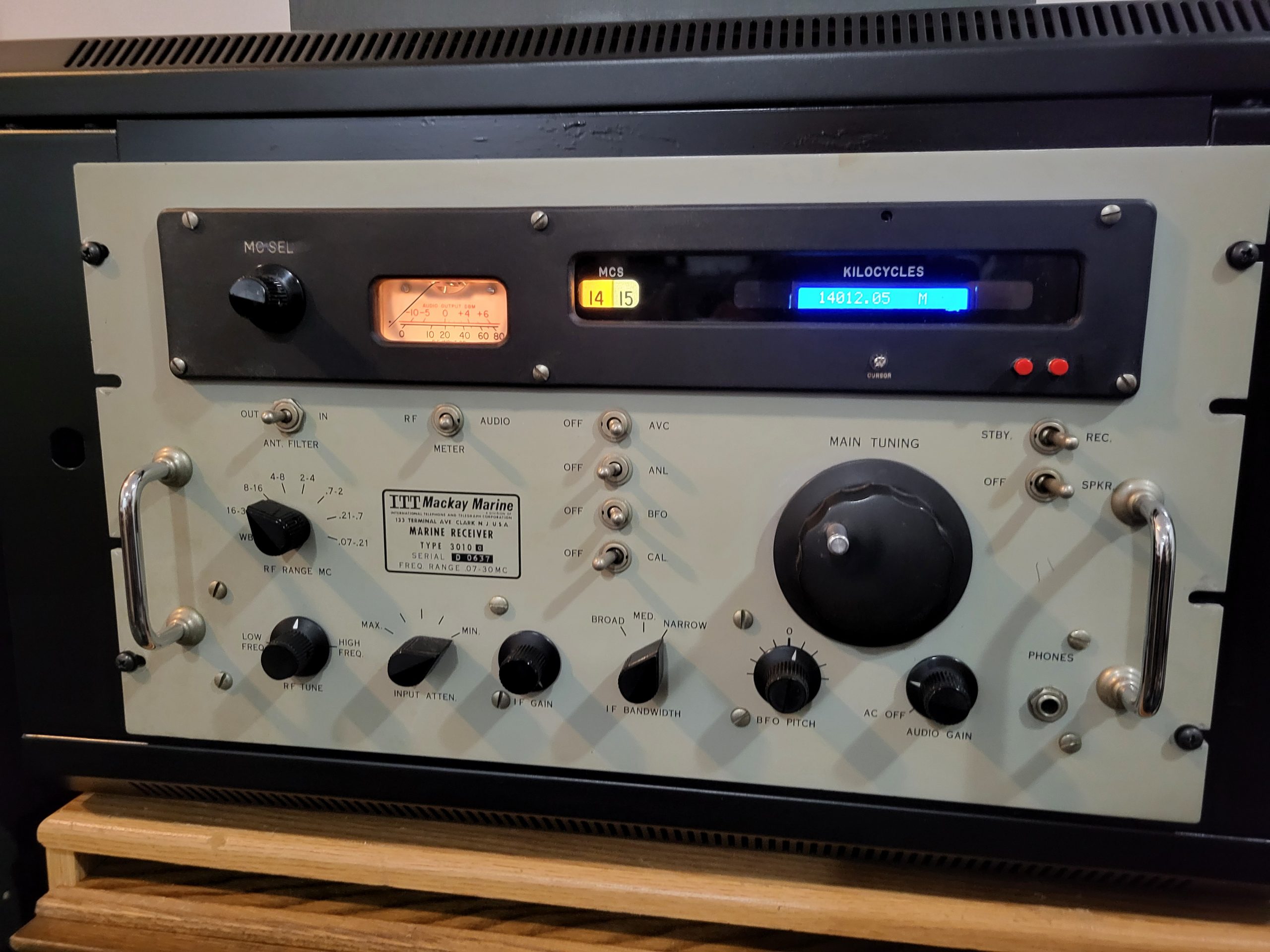
The 3010C was one of the last commercial communications receivers developed using vacuum tube technology. Its first mixer was a modern diode ring mixer. It also used one of the last vacuum tube developments, the 7788 as its rf amplifier. When introduced around 1967, it was the pinnacle of vacuum tube technology.
Performance Issues
The 3010C HF oscillator performance is severely degraded over time because of crystal aging resulting in lower output. Eventually, the HF oscillator no longer functions. This usually occurs on the highest frequency bands initially. Another culprit is the first HF mixer. The mixer uses hand selected uhf germanium diodes whose operating characteristics change over decades such that mixer balance is severely compromised. Finally, the frequency readout dial strip stretches and eventually wears out. There are other issues that aren’t related to component aging. The frequency dial resolution and the frequency tunability is too coarse for crowded situations such as DX contests.
Modifications
The modifications are: 1) Replace all of the aging HF oscillator crystals (15) and the HF oscillator tube with a Si5351 synthesizer oscillator. 2) The Si5351’s rf output is amplified to a +7dbm drive level at 50 ohms with a Mini-Circuits ZFL-1000 wideband amplifier. 3) Replace the first HF mixer with a Mini-Circuits +7 dbm double balanced ring diode mixer module, the SRA-6 or equivalent. The SRA-6 is no longer produced, so another +7dbm mixer whose frequency specs match the LO, RF, and IF ports will work fine. 4) Replace the VFO tube oscillator with and its associated circuitry with an AD9951 DDS VFO oscillator. 5) Replace the frequency dial tape and its associated mechanical components with an LCD display. In order to facilitate these modifications, an Arduino 2560 Mega microcontroller is used to control the oscillators and display the frequency. These modifications resolve all of the above problems.
Results
Previously, the 3010C was dead above the 12-14 mhz band due to dead HF oscillator crystal. Now, the 10-meter ham band comes alive with excellent sensitivity. The receiver was used in the ARRL CW contest with excellent results. Using the stock Collins 500hz mechanical filter, no dynamic overload or IMD products were noticed. Obviously, you won’t be able to use this in a multi-multi contest station. The DDS synthesizer produced no birdies compared with the several birdies noted with the original triangle wave shaped VFO tube oscillator. Frequency resolution is now stable at 10hz resolution with plenty of tunability for CW signals.
Circuit Descriptions
HF Oscillator:
Referring to the circuit diagram below, the Si5351 synthesizer produces a square wave output that is good to 150mhz. A square wave is preferable to a sine wave for driving a ring diode mixer. The Si5351 can have good channel cross talk performance with a couple of caveats: 1) the output should be capacitive coupled. 2) the output impedance should be kept > 1k ohms. It will operate into a 50-ohm load, but the cross talk between channels will be lowered. The ZFL-1000 has the necessary bandwidth to amplify a square wave without distortion into the Vhf range with a 50-ohm output impedance. The highest square wave frequency required is near 70mhz so an amplifier that can amplify a signal into the 500mhz range is required. To set the proper output level to the HF diode ring mixer, connect a 50ohm resistor to the output of the 2k pot and adjust for a level of 800mv peak. Remove the resistor and connect to the mixer LO port. The Si5351 IC is controlled via the I2C serial bus by the Arduino 2560 microcontroller.
VFO Oscillator:
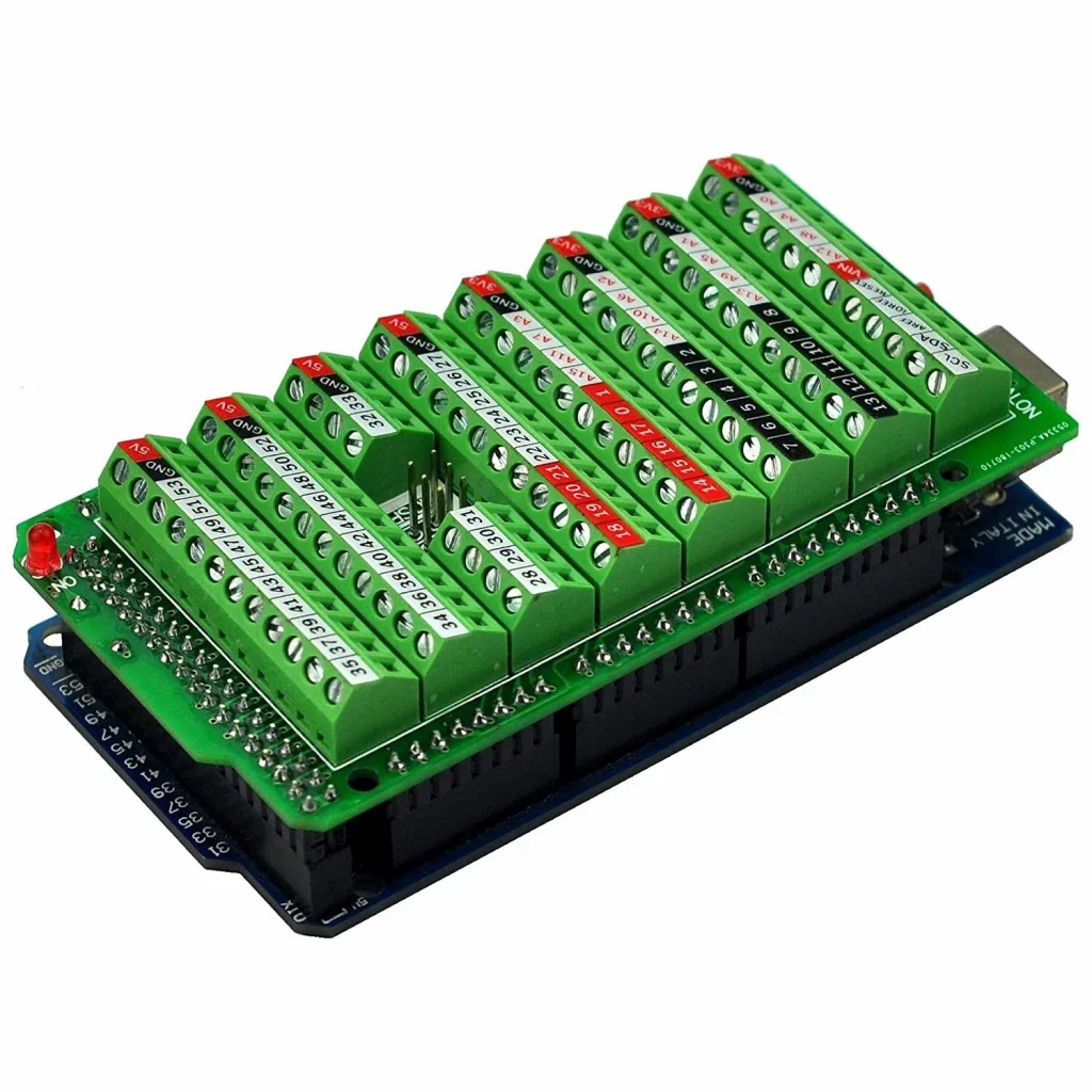
The AD9951 DDS oscillator function is handled by the WA1FFL AD9951 DDS board. When ordering the board, do not order with the micro-controller installed since the Arduino 2560 will be controlling the AD9951. In addition to the AD9951, the WA1FFL board contains all of the different voltage regulators required by the AD9951, contains all of the low pass filters , and amplification necessary to supply 750mv at 75 ohms for the 3010C VFO circuit. Using hookup wire, connect the Arduino outputs to the appropriate WA1FFL microcontroller socket hole and solder. Note that using an Arduino breakout terminal strip shield greatly facilitates this process. See the below picture of this shield. Use the WA1FFL documentation to help with this process.
Arduino 2560 Mega Controller and LCD Display:
Using the previously mentioned terminal board shield for wiring up the I/O for the 2560 is a necessity. See the picture of this shield for assistance in purchasing this item on Ebay. Note that the 2560 is fed with 8v instead of 13.8v. This is done to reduce the power dissipation of the 2560’s internal 5v regulator. The 3010C band switch position selector switch uses a voltage divider and an analog input of the 2560 to determine the selected 2mhz band segment. One +5v line and one analog input line is used instead of 15 wires going to 15 digital inputs. A 16×2 LCD display with an I2C serial interface is used to display the frequency. A custom-made aluminum frame holds the display to the front panel. All of the frequency dial tape hardware has to be removed. Thin cardboard wrapped in black tape covers the dial window areas not filled by the LCD display.
Skill Level Required:
This project is definitely not a plug and play turnkey project. The skill level requires decent soldering skills and some experience with kit building. Although not requiring any programming skills, the ability to understand basic Arduino microcontrollers and download an Arduino program via the USB interface and Arduino IDE will be necessary.
Right: Arduino Mega 2560 Screw Breakout Board that can be found on Ebay.
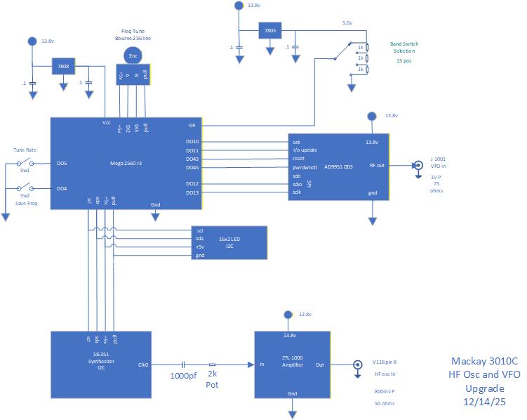
System Diagram
This shows the connections between the Arduino 2560 Mega microcontroller, the HF Oscillator synthesizer, the DDS VFO, LCD display, and the miscellaneous I/O components
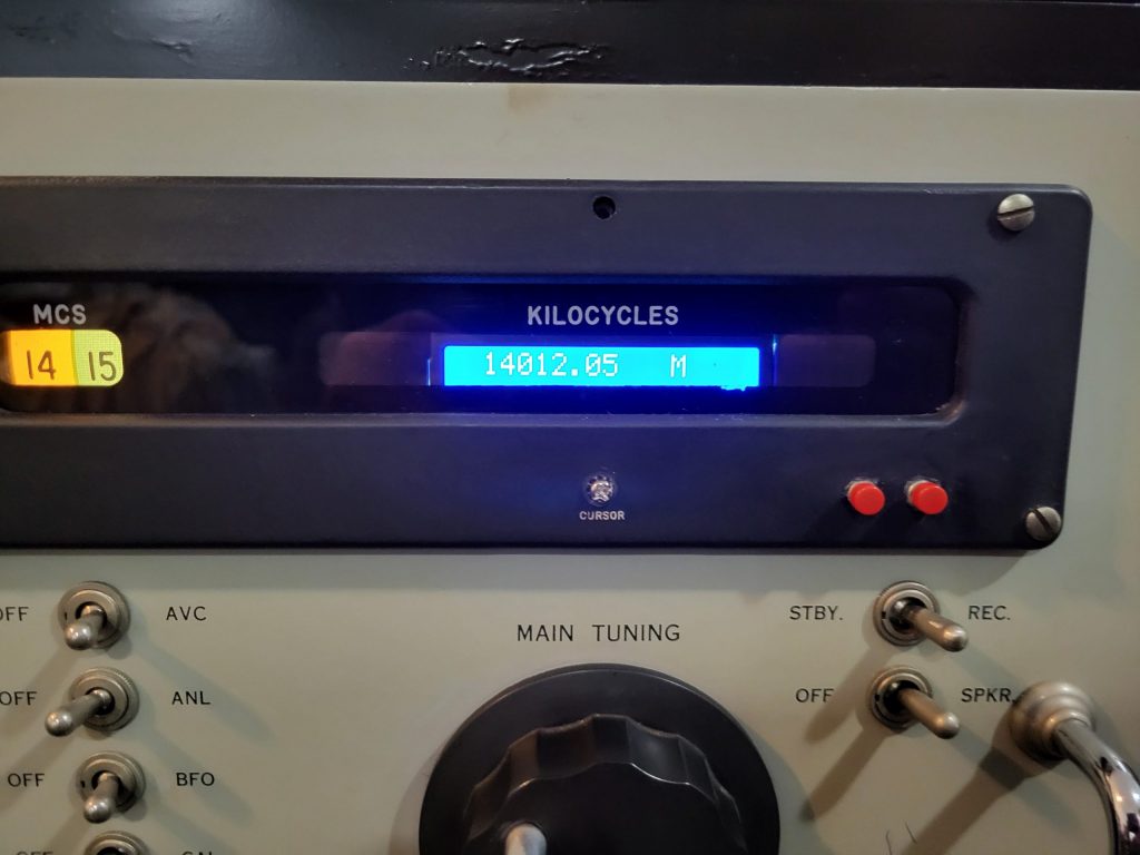
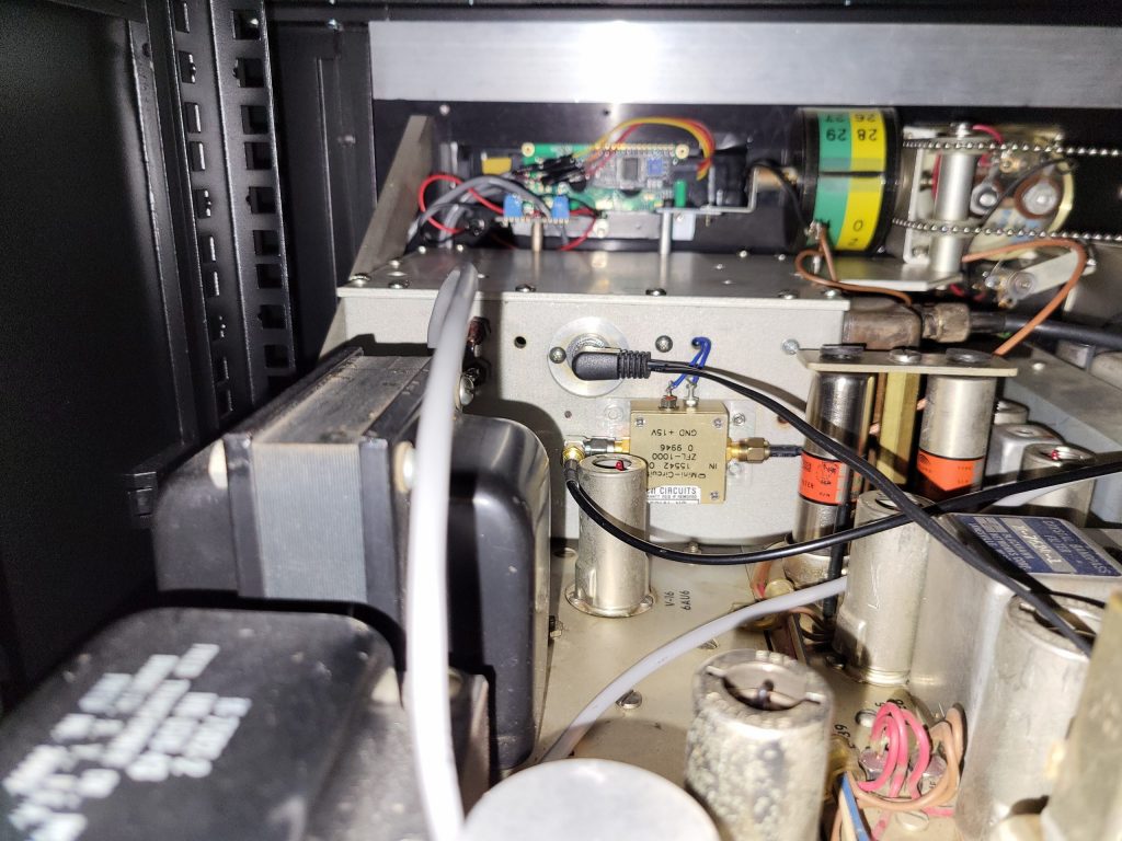
Above: Front Panel LCD 16×2 display. Right: Top View of VFO enclosure showing pb I/O interface board
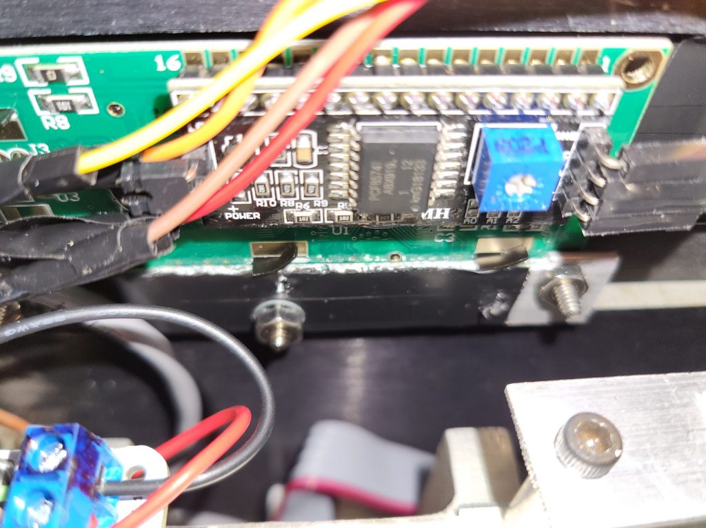
Right: LCD mounting
Right: Rear view looking a VFO enclosure
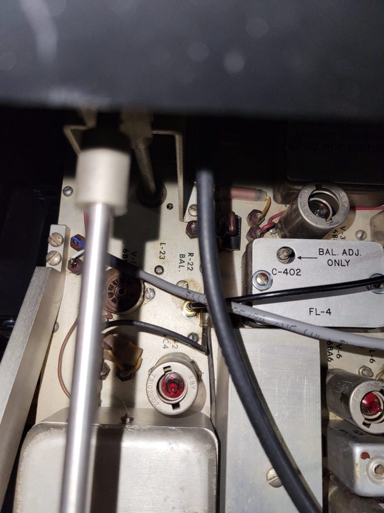
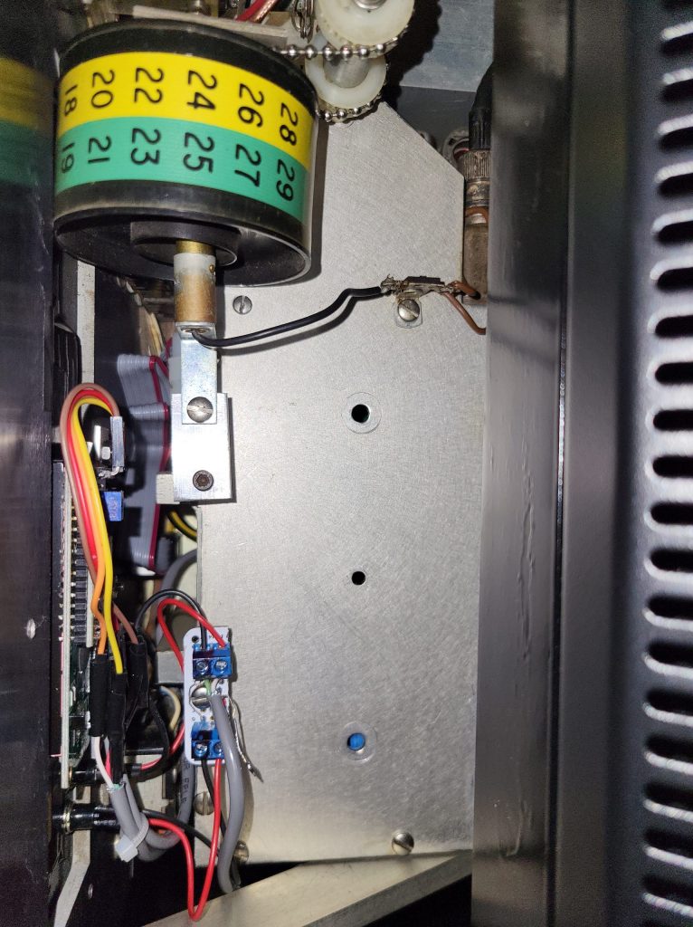
Right: Top view of HF oscillator tube area. The tube is permanently removed and the HF oscillator signal from the Si5351 synthesizer is fed into the old HF oscillator section through the SMA chassis connector that is located just to the right of the 6C4 tube. There is an existing hole from a screw that’s no longer needed. Note that the two feed thru capacitors no longer supply filament power or HV to the HF oscillator tube since it is no longer used. Instead, the blue wire supplies +5v to the voltage divider network and the white wire is the band switch rotor which supplies the 0-5v signal to the analog input of the Arduino 2560 microcontroller.
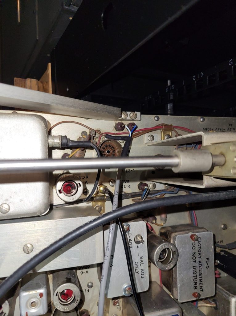
Right: Another top view of the HF oscillator area.