Collins HF-8014A Exciter Thumb wheel Replacement
The HF-80 system was a major military/government communications platform, but its adaptability Ham radio can be an issue. The cumbersome thumb wheel channelized method of frequency adjustment is not practical for normal ham radio use. This page will discuss a tuning thumbwheel replacement that does not deface or require any mods to the Exciter: it is entirely reversible. If fact, the only modification to the HF-8014A Exciter, is to disconnect the ribbon cable from the thumb wheel board and bring it out the back of the receiver.
Detailed Discussion
There is no way to get around the complexity of the HF-80 system and the extensive document manuals illustrate this point. This page and others are an attempt to reduce the complexity to a practical level. The HF-80 system receiver and exciters can be integrated using the HF8096 remote controller, but besides the cost of acquiring the HF-8096, you still have the problem of the cumbersome channelized frequency control. Still another issue for practical ham radio use, is that the exciters nominally output 250mw. Unless you have the HF-802x PA, which is not cheap, a standard ham radio linear amplifier will not work directly with these exciters. In conclusion, these issues represent a significant barrier to entry for most radio amateurs. The purpose of these series of HF-80 related pages is to significantly reduce these barriers to entry and make the HF-80 system practical for ham radio through the use of an Arduino based microcontroller.
System Controller
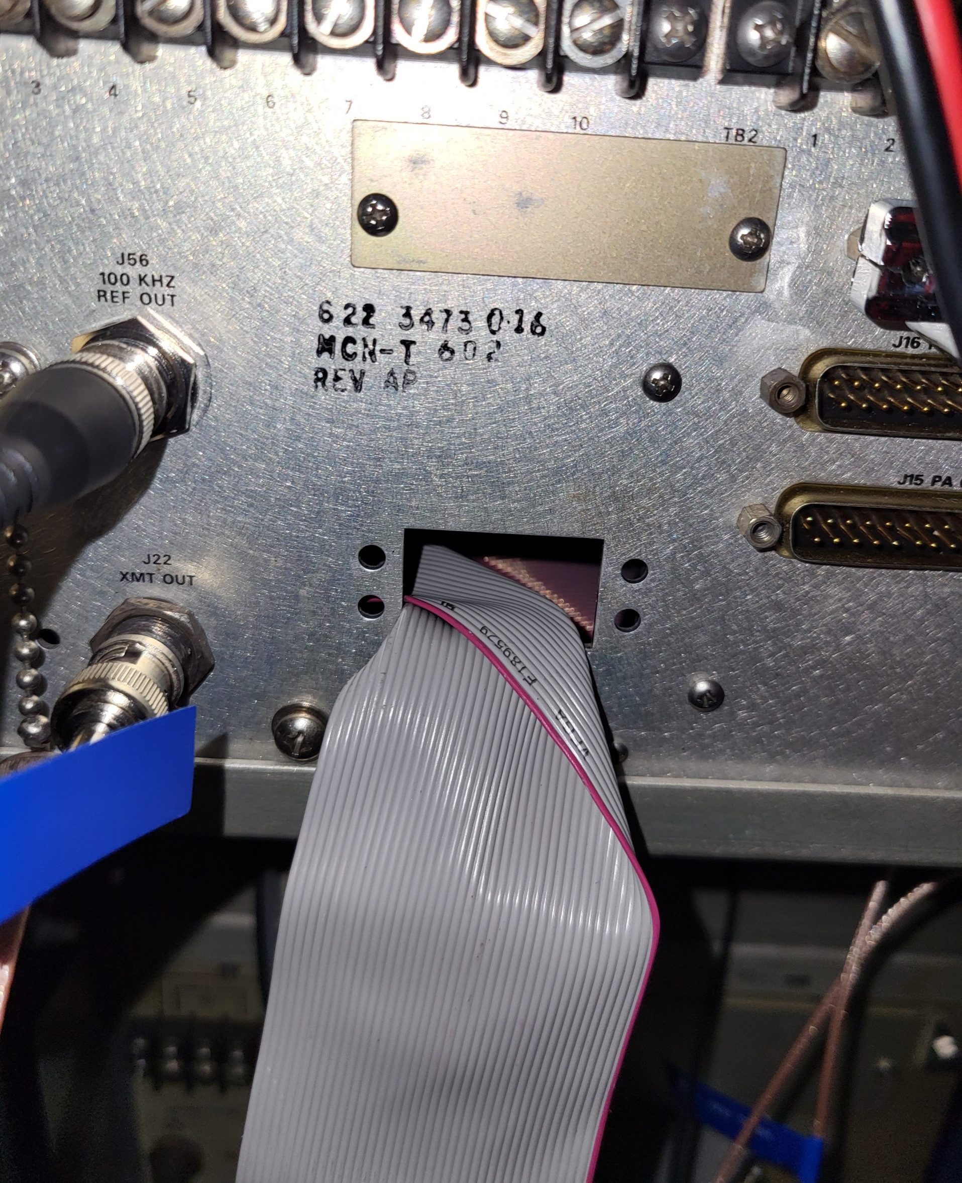
The system controller replaces the HF-8014A exciter frequency thumbwheel selection with a system controller that can copy instantly the receiver frequency to the exciter. In standalone mode, the exciter frequency can be varied with an encoder based tuning knob. The modification consists of disconnecting the ribbon cable from the thumbwheel board and re-routing it to the back panel and pulling it through an unused db style connector hole. Folding the ribbon near the connector into a right angle and then pushing the end of the ribbon cable sideways through the hole will get the connector through the hole even if the connector is wider than the hole.
This IDE-40 ribbon cable is connected to an extender cable that feeds into the system controller box where an IDC-40 ribbon cable breakout module interfaces the ribbon cable to the Arduino 2560 microcontroller. The Arduino 2560, using an encoder and/or a keypad to provide frequency input information, outputs the proper frequency in BCD coded parallel format that exactly emulates the thumbwheel. The receiver remains in local mode and the rest of the receivers front panel controls function as normal.
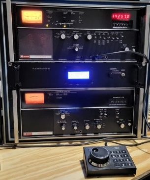
The system controller through a second Arduino 2560 also provides the same function to the HF-8014 exciter, thus providing frequency control integration for both receiver and exciter. The current receiver frequency is indicated on a 4×20 character LCD display as well as the receiver LED display. Since the receiver LED display is an option on some receivers the separate LCD frequency display has this scenario covered. Frequency step size can be selected by a push button. I use a Ten-Tec 302R encoder/keypad. I wanted this device to be close to the operators position as possible without having to reach up to the controller box.
This IDC-40 ribbon cable is connected to an extender cable that feeds into the system controller box where a IDC-40 ribbon cable breakout module interfaces the ribbon cable to the Arduino 2560 microcontroller. To the right: the IDC-40 ribbon cable exits the rear panel of the HF-8014A.
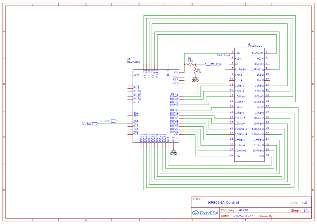
System Controller Schematic
To the right is the system controller schematic. In the center is the Arduino 2560 Mega microcontroller. To the right of it is the 40 pin IDC breakout module.
The Arduino 2560 that controls the HF-8014A frequency, communicates with the HF-8050A main 2560 microcontroller via its serial port. The two microcontrollers use +5v instead of RS232 voltage levels because the distance is a matter of inches. The HF-8014A 2560 monitors serial port 1 for any new data packets and then checks for a valid frequency command. By continuously monitoring, the frequency can be a one-time channelized frequency command or it can be a series of commands to perform a frequency spot sequence.
For the System Controller display and the controller component layout, refer to the HF-8050A page for a detailed explanation.
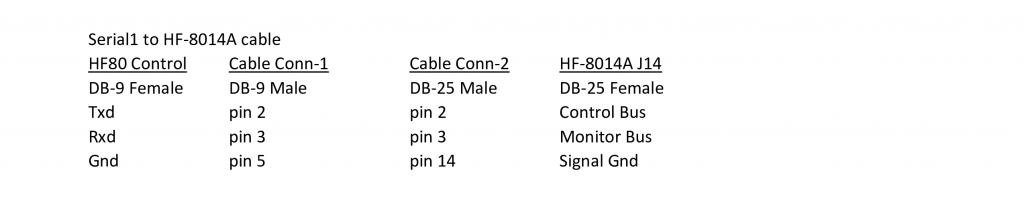
Serial Communication to System Controller
The System Controller uses serial communication with the HF-8014A to get Monitor Status information, specifically the current Mode and PA Status. The serial protocol used is the 8-bit HF-80 Word protocol (not the 7-bit ASCII protocol). The serial port configuration is 9600 baud, 8 data bits, odd parity and 1 stop bit. The HF-8014A serial card configuration switches must be set as follows: S1) Switch 2 closed, all others open. S2) All switches open. S3) Switch 5,6 closed, all others open. S4) Switch 5,6 closed, all others open. This Monitor Status information is used for LCD display purposes only and is not required for frequency control.