Collins HF-8050A, HF-8054A Receiver Thumb wheel Replacement
The HF-80 system was a major military/government communications platform, but its adaptability Ham radio can be an issue. One issue is the complexity, another is receiver/transmitter integration, another is cost because of the required PA unit and finally, the biggest issue is the lack of receiver tuning ability. These receivers lack the tuning characteristics of the 851S-1 receiver. The cumbersome thumb wheel channelized method of frequency adjustment is not practical for normal ham radio use. One hams comment kind of sums it up: “I have an HF-80 system that I actually use”. This page will discuss a tuning thumbwheel replacement that does not deface or require any mods to the receiver: it is entirely reversible. If fact, the only modification to the HF-8050/8054 receiver, is to disconnect the ribbon cable from the thumb wheel board and bring it out the back of the receiver.
Detailed Discussion
There is no way to get around the complexity of the HF-80 system and the extensive document manuals illustrate this point. Having the manuals on the Collins Collector Website would help (Jan/2026). This page and others are an attempt to reduce the complexity to a practical level. The HF-80 system receiver and exciters can be integrated using the HF8096 remote controller, but besides the cost of acquiring the HF-8096, you still have the problem of the cumbersome channelized frequency control. Still another issue for practical ham radio use, is that the exciters nominally output 250mw. Unless you have the HF-802x PA, which is not cheap, a standard ham radio linear amplifier will not work directly with these exciters. In conclusion, these issues represent a significant barrier to entry for most radio amateurs. The purpose of these series of HF-80 related pages is to significantly reduce these barriers to entry and make the HF-80 system practical for ham radio through the use of an Arduino based microcontroller.
System Controller
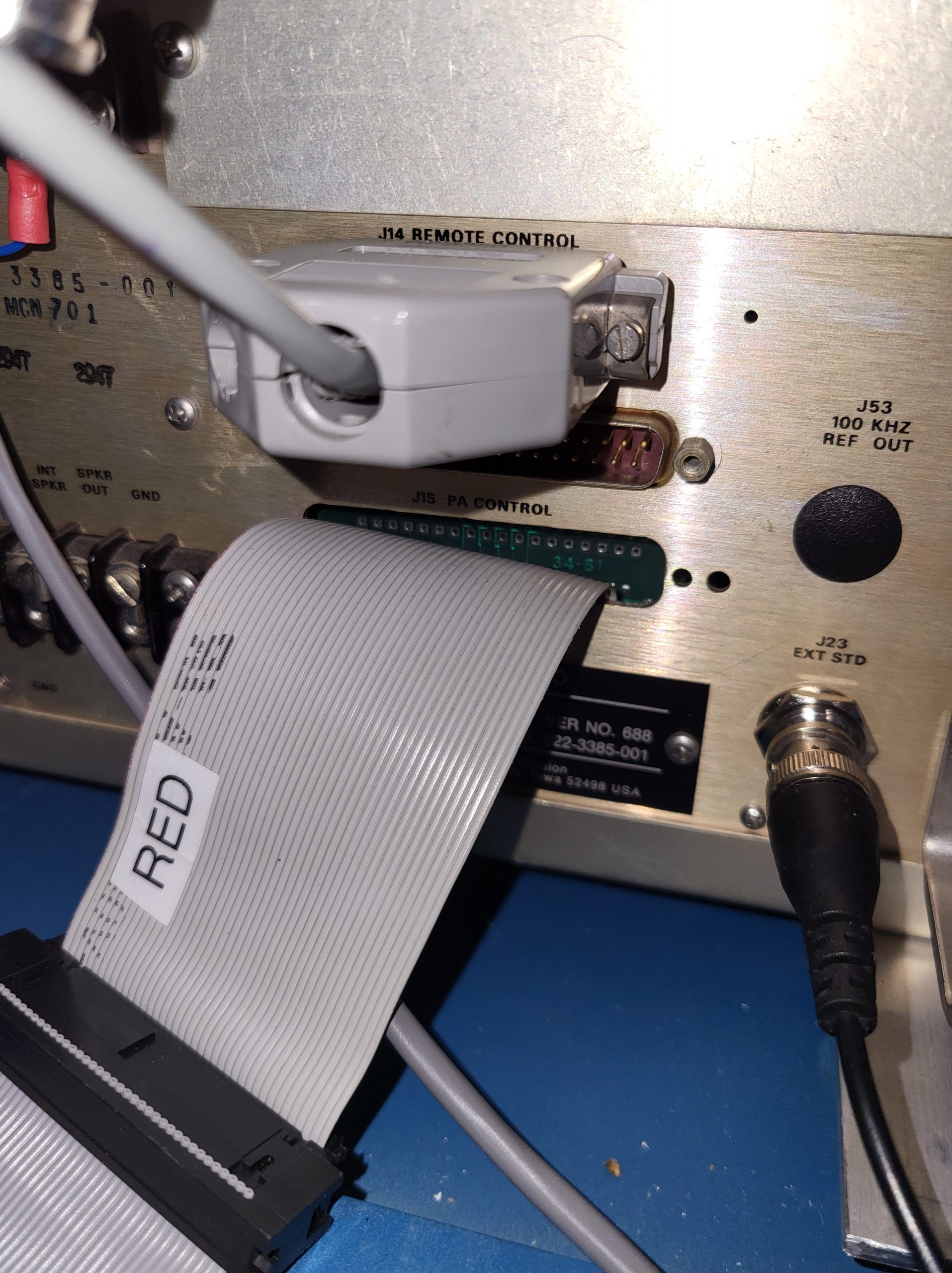
The system controller replaces the HF-8050 receivers thumbwheel with an encoder based tuning knob. This modification consists of disconnecting the ribbon cable from the thumbwheel board and re-routing it to the back panel and pulling it through an unused db style connector hole. Folding the ribbon near the connector into a right angle and then pushing the end of the ribbon cable sideways through the hole will get the connector through the hole even if the connector is wider than the hole.
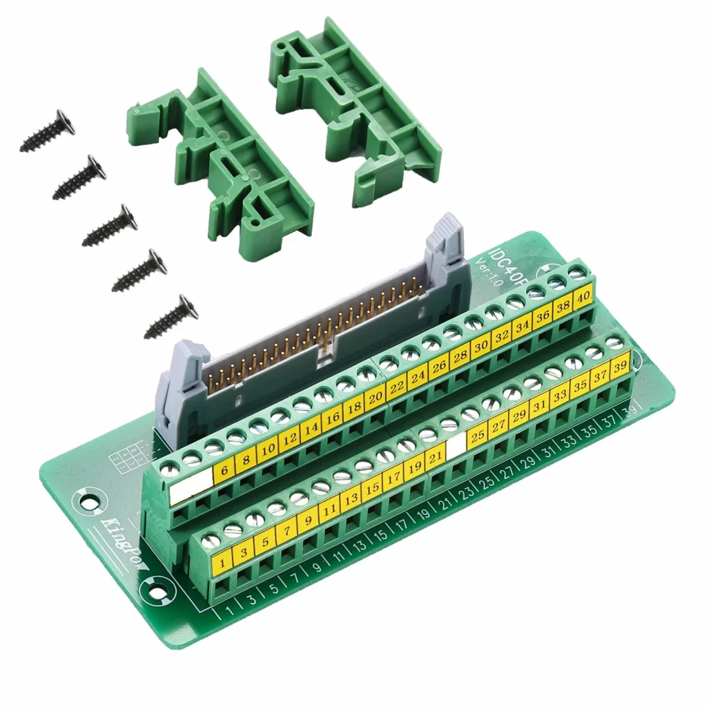
This IDE-40 ribbon cable is connected to an extender cable which feeds into the system controller box where a IDC-40 ribbon cable breakout module interfaces the ribbon cable to the Arduino 2560 microcontroller. To the right: the IDE-40 ribbon cable exits the rear panel of the HF-8050A.
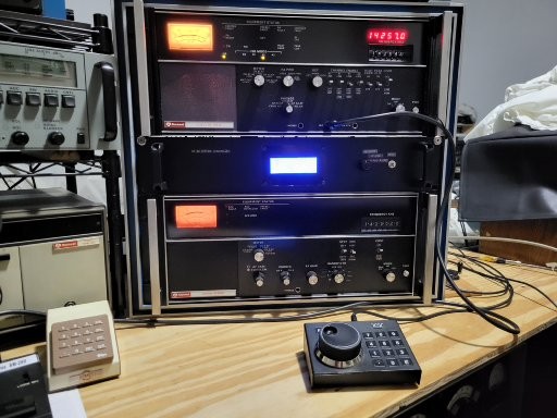
The Arduino 2560, using an encoder and/or a keypad to provide frequency input information, outputs the proper frequency in BCD coded parallel format that exactly emulates the thumbwheel. The receiver remains in local mode and the rest of the receivers front panel controls function as normal. The system controller, through a second Arduino 2560, also provides the same function to the HF-8014 exciter, thus providing frequency control integration for both receiver and exciter. The current receiver frequency is indicated on a 4×20 character LCD display as well as the receiver LED display. Since the receiver LED display is an option on some receivers the separate LCD frequency display has this scenario covered. Frequency step size can be selected by a push button. I use a Ten-Tec 302R encoder/keypad. I wanted this device to be close to the operators position as possible without having to reach up to the controller box.
LCD Display Layout
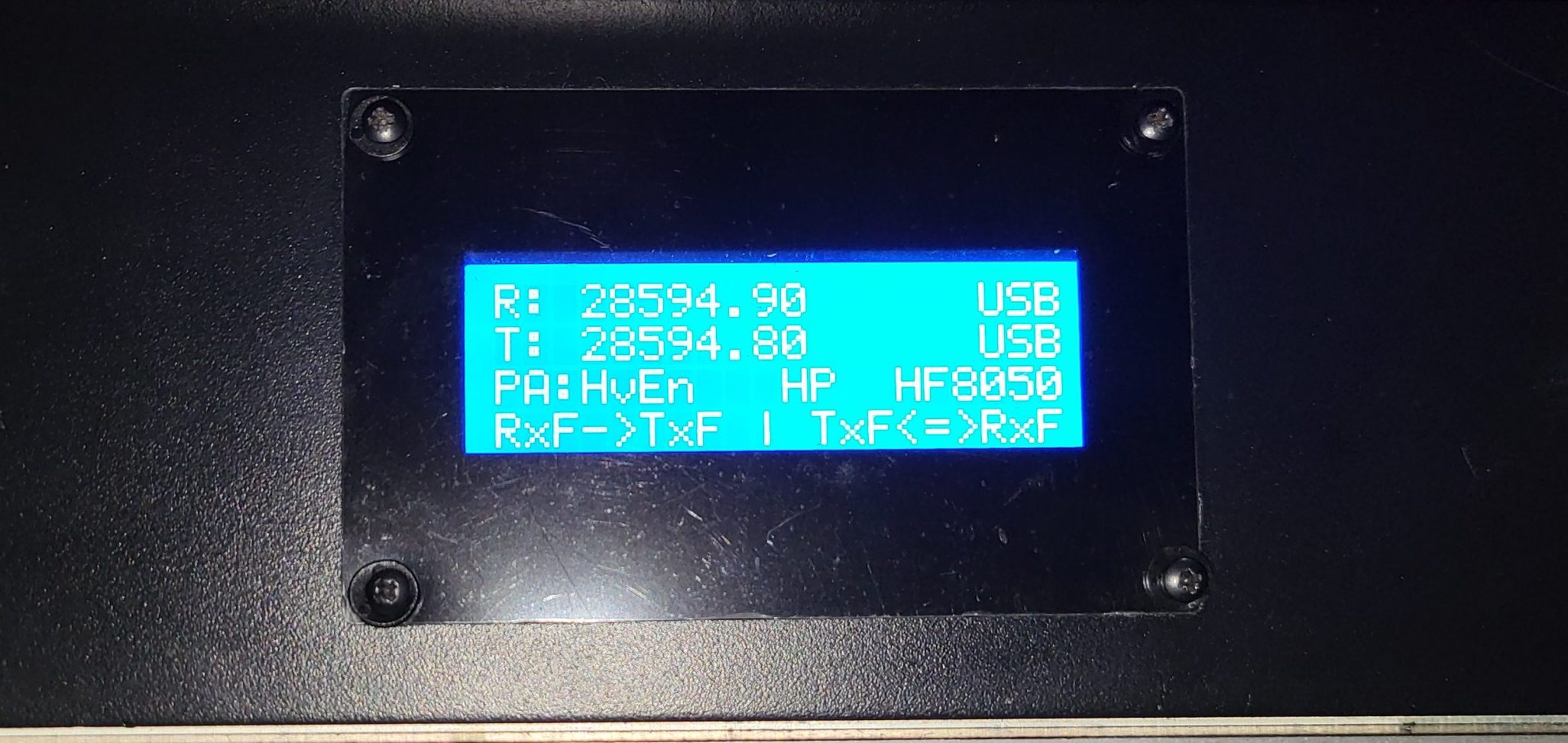
The first line of the display is the receiver frequency. The second line is the HF-8014A current frequency. Note that the exciter frequency does not automatically change when the receiver frequency changes. It only changes when the RxF->TxF function is selected by pushing the F1 key on the keypad. The reason for this is that each time the exciter’s frequency is changed, a tune cycle is initiated if an HF-80 PA or antenna coupler is being used. This function takes the receiver’s current frequency and sets the exciter’s frequency to match. Line 3 is the PA status. Since there are only three function keys on the Ten-Tec 302R, they have to be multiplexed because there are more than three functions that have to be selected. The fourth line shows the current function key group selected. Function key 3 is permanently assigned to incrementing the next group. F1 and F2’s current function is separated by the vertical dash.
System Controller Schematic
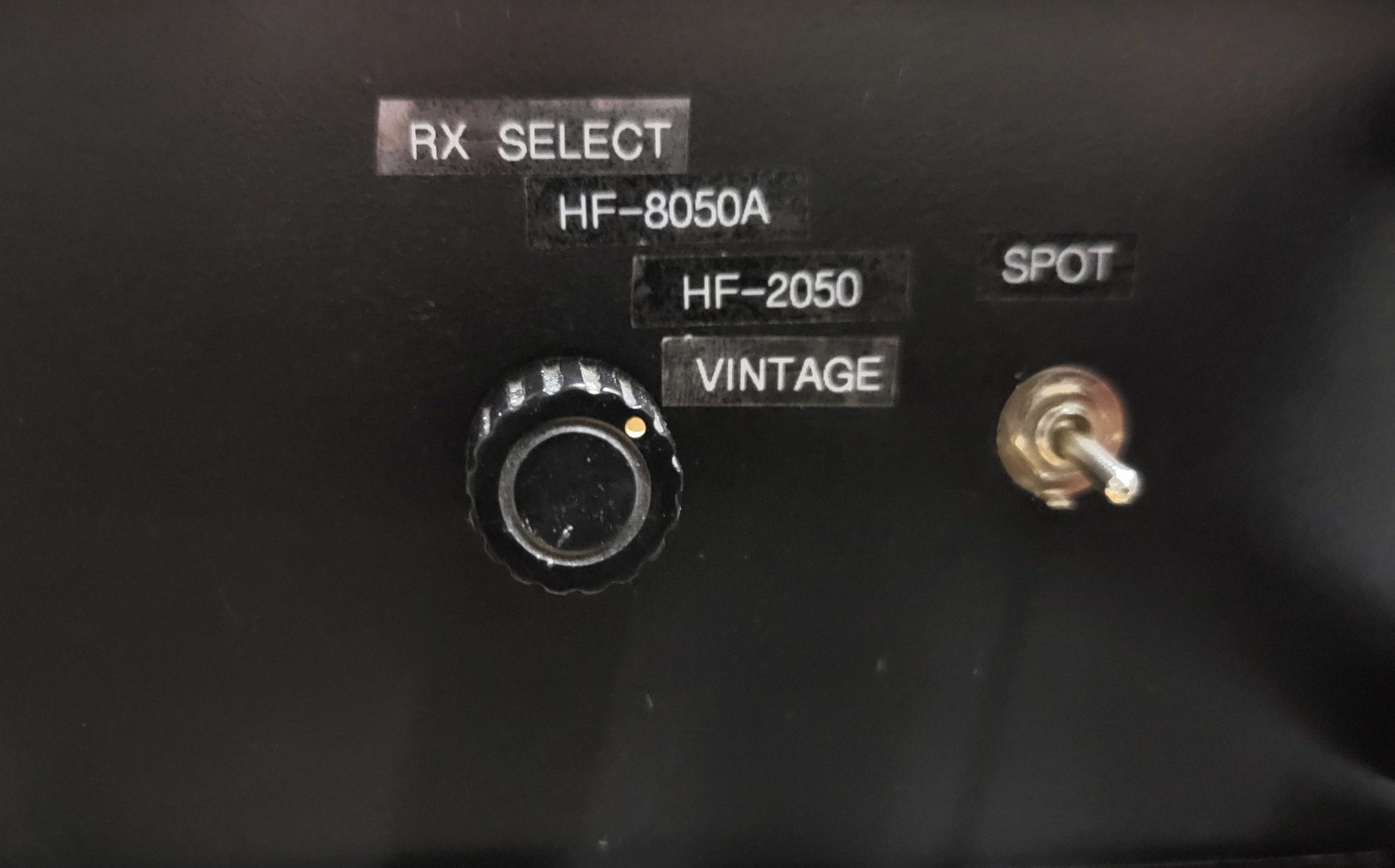
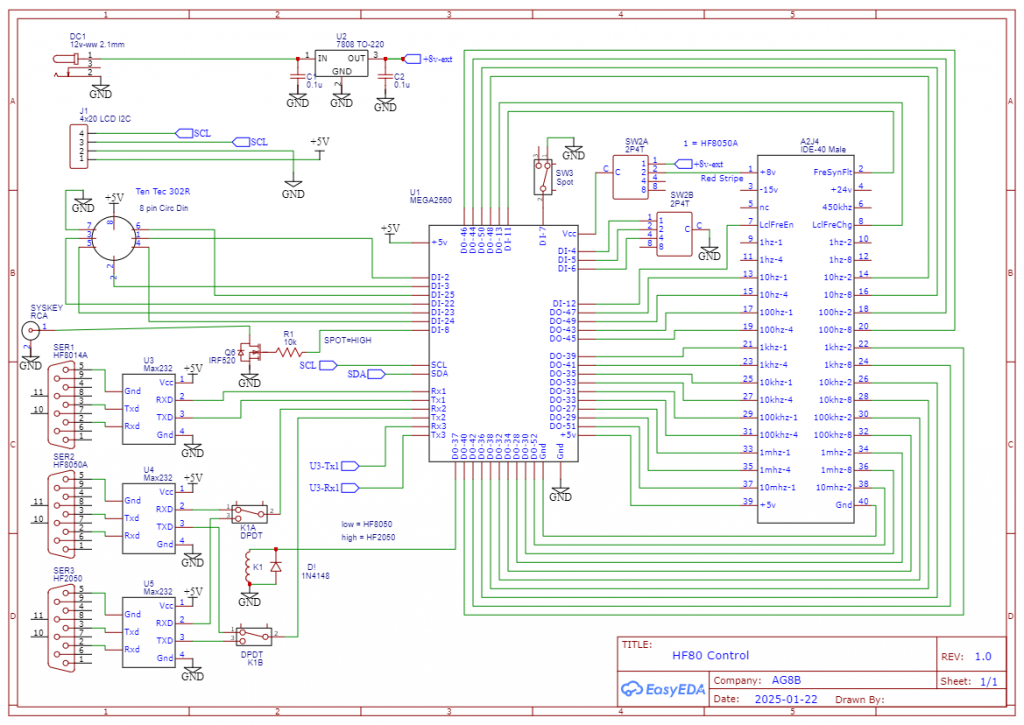
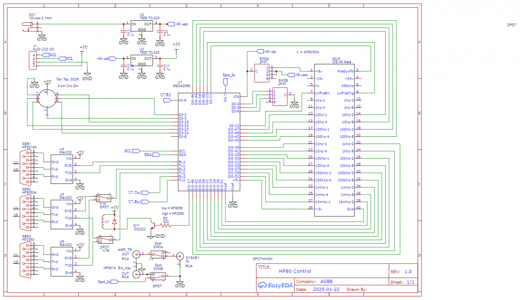
To the right is the system controller schematic. In the center is the Arduino 2560 Mega microcontroller. To the right of it is the 40 pin IDC breakout module. To the left is the serial ports, tuning encoder and I2C LCD display interface. The 2P4T selector switch, SW2A and SW2B is used to select the active receiver. Active receivers can be the HF8050, HF2050, or vintage receivers such as the 651S1 or HRO500. For these types of receivers, a frequency spot switch is necessary to get the exciter on the receiver’s frequency. Switch SW3 is the spot switch. This switch disconnects SYSKEY from the PA T/R line and grounds the HF-8014A Ext Key input, thus keying the exciter without keying the PA. Since the PA mutes the receiver, the receiver remains unmuted and receives the exciter’s 250mw Spot signal.
Arduino System Controller Build
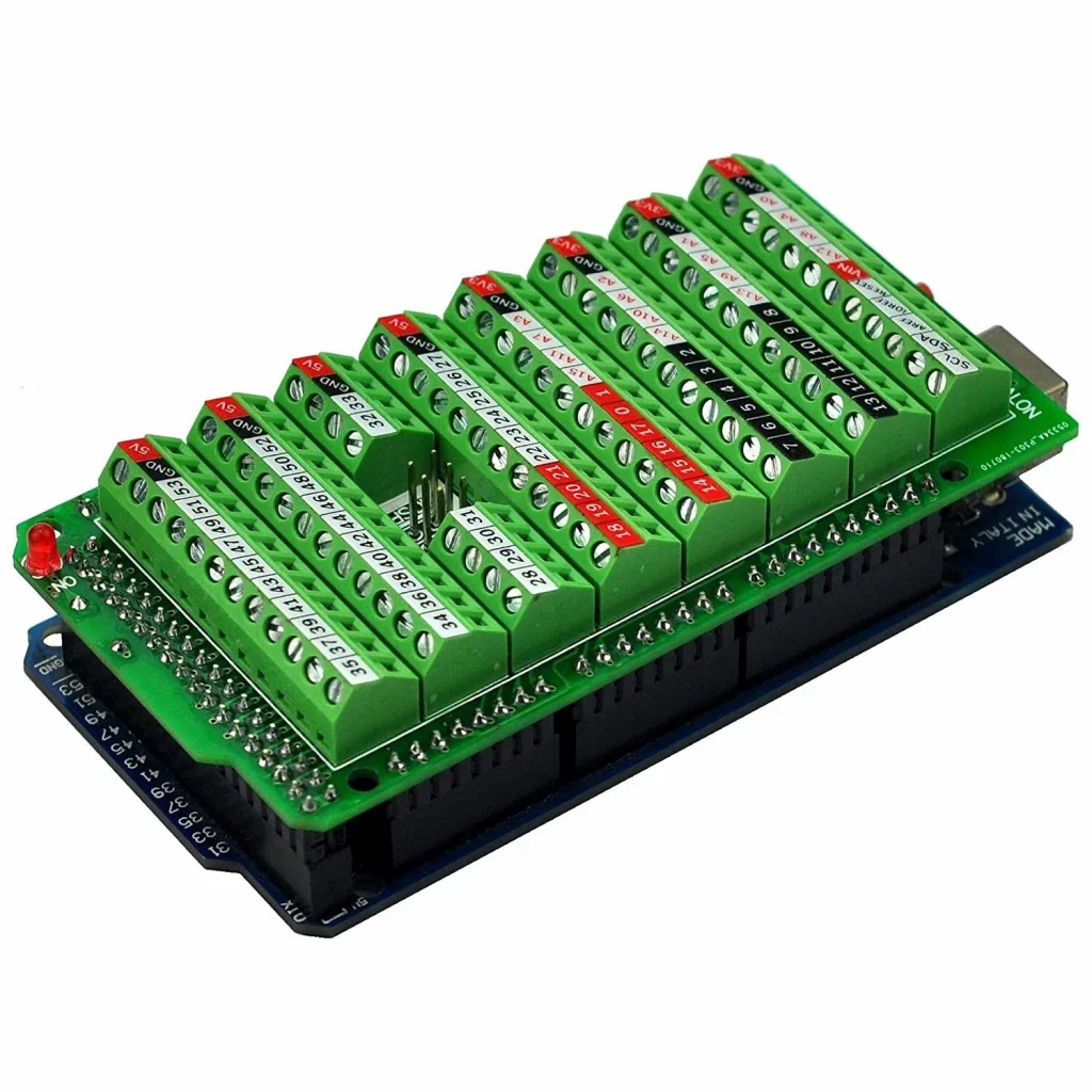
This is not a turnkey project that you can purchase as a kit. The Arduino micro controller family has been used extensively in ham radio projects. Several books have been written about Arduino based Ham radio projects and there are many YouTube tutorials available. These controllers and their associated I/O called “shields” are very building block oriented. It isn’t necessary to write any code for this project, simply download the software files for this project to the Arduino 2560 microcontroller, through the Arduino USB cable with a PC. The IDC-40 breakout connector can be bought on Ebay. See the attached picture. Standard 10 and 20 cm Dupont jumpers are used to connect the 2560 I/O to the IDC-40 breakout module. The IDC-40 pin extender cable needs to be a female to male 2-3 feet long cable. Note that the cable must include pin 20. Some IDC extender cables used on SATA drives exclude pin 20. The CablesOnline p/n is: FI-024. The IDC-40 breakout board connects to the Arduino 2560 via Dupont 10 cm male/male jumpers. The Arduino 2560 has a terminal breakout shield (shown below the IDC-40 board) mounted to it which facilitates attachment of the Dupont jumpers. See the Excel spreadsheet in the Download zip file, in the tab called FreqSel1 for specific connection information.
The encoder chassis connector is an 8-pin circular DIN female chassis mount connector. See the picture for the pinout for the Ten-tec 302R encoder/keypad. Even though the Arduino software is setup for the Ten-tec 302R encoder/keypad, any 256-line incremental encoders like the Bourns ENS1D-B28Y00256L would work. See the aforementioned Excel spreadsheet and tab for specific connection information.
The RS-232 converters are based on the MAX232 chip and already have the DB-9 female connector mounted to the board. Make a cut out for the DB-9 connector and mount the entire to the chassis. Use four Dupont jumpers to connect to the 2560. Since Vcc and Gnd are used on all three MAX232 RS232 modules, a Vcc and Gnd distribution header will simplify the wiring. Solder the male end of a male/female Dupont jumper on a section of prototype board and the female end connects to the .1 header male pins on the RS232 module. Note that the RS232 communications is used for getting status information only from the HF-8050A or HF-8014A so that this information may displayed in a central location. The RS232 lines are not used for any control.
System Controller Layout
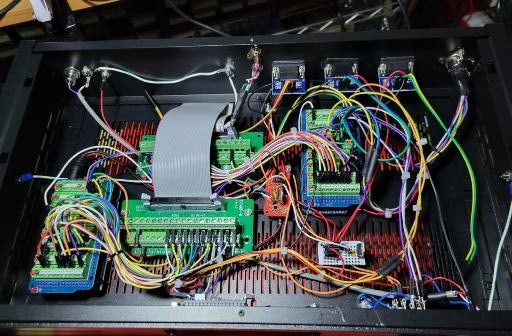
This shows the controller chassis layout from a top front view with the front panel removed. The receiver Arduino 2560 is shown on the right and the exciter Arduino 2560 is shown on the lower left. The IDC-40 breakout module for the exciter is on the bottom and the one for the receiver is above it in the picture on the right. The small red prototype board distributes +8v to the two Arduino 2560. The small white prototype board distributes Gnd and +5v. The three RS232 boards are mounted to the chassis in the upper part of the picture. The 8-pin circular DIN chassis connector for the encoder/keypad is shown in the upper right corner.
Miscellaneous
The power for the Arduino controller comes from the HF-8050A +8v which is located on pin 1 of the IDC-40 breakout module. This is not only convenient, but it allows the receiver and the controller to power up simultaneously. If they don’t power up at the same time, a couple of issues can occur. First, if the HF-8050 powers up before the 2560 controller, +5v power can come through an I/O port into the 2560 controller. This is a quirk in the Arduino family. If the current draw is high enough for long enough, the I/O port can be damaged. If the 2560 is powered up first and then the receiver, there can be an issue with the receiver Sys Fault not able to be cleared on power up. Again, powering both systems up simultaneously takes care of both of these issues.
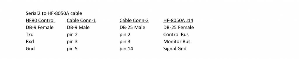
At the point where the ribbon cables exit the system controller chassis, a small chunk of the aluminum chassis need to be nibbled off so that the cover can sit flush with the chassis. The serial cables require only a few wires for each cable. The Excel spreadsheet, HF80 Notes, HF80 Cables tab, in the Download zip line contains all of the information for building these cables. If you use crimp style pins, no soldering is required and the process of building the cables is fairly quick. One last caveat: when connecting the IDC-40 pin ribbons cables, make sure that the red wire is oriented the same on both cables.
Serial Communication to System Controller
The System Controller uses serial communication with the HF-8050A to get Monitor Status information, specifically the current Mode. The serial protocol used is the 8-bit HF-80 Word protocol (not the 7-bit ASCII protocol). The serial port configuration is 9600 baud, 8 data bits, odd parity and 1 stop bit. The HF-8050A serial card configuration switches must be set as follows: S1) Switch 2 closed, all others open. S2) All switches open. S3) Switch 5,6 closed, all others open. S4) Switch 5,6 closed, all others open. This Monitor Status information is used for LCD display purposes only and is not required for frequency control.